I have gone through many iterations in the applications that drive my Home Automation (HA) system but so far I have held firm to the underlying Insteon technology that powers it. A long-standing goal for moving to the next level has been to interface my Ademco Alarm panel into my HA system so I can take full advantage of the sensors that feed the Ademco system to make my HA setup even better. The fundamental challenge in making this happen is that these two systems are completely different which requires the use of other technologies to bridge them together.
In my last post I wrote about interfacing my Insteon Powerlinc Module (PLM) to my Mac so I could use Indigo to drive my HA system. The next step was to find a way to capture messages from my Ademco alarm panel so I could make full use of the extra data in my home automation scripts. Achieving this goal was much more of a challenge than it might initially seem. While researching my interface options, I quickly discovered that those options were very limited.
- VISTA-ICM: Until early 2010 Honeywell licensed a third party (i2networks) to produce a module that could have been leveraged to achieve our goals but due to a disagreement between the companies, the unit is no longer available and finding an unused unit has become a challenge.
- VISTA X10 Module: Honeywell makes an X10 Module that can send X10 messages when certain events occur. My concern with this approach is that it required programming changes to the alarm panel and then there’s the issue with X10 reliability.
- Build an Interface: Since I couldn’t find any other connectivity methods, my thought was to build my own device and try and capture the raw ECP bus traffic, parse it and then feed it into Indigo. Info on this thread indicated how challenging that approach might be since the details of the ECP protocol are not publicly available.
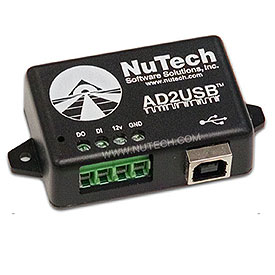
- AD2USB: While researching options I ran across a little device that wires into the Ademco Panel like a keypad and provides an easily parsable stream of data that can be used by any system that can read a serial stream.
After considering all of these options, I decided to start with the AD2USB. The biggest factor in going down this path was the amount of time that would be required to build my own solution would significantly outweigh the sub $100 investment it would take to purchase this device.

Following are the steps I took to set up my AD2USB.
Step 1 – Call off the hounds
Before you do any work on your alarm system, it’s imperative that you contact your monitoring company and tell them to put your system on “disregard” while you’re working on your panel.
Step 2 – Kill the power
Working on a powered system is never a good idea. To reduce the risk of shock and to minimize the chance of a short or otherwise causing damage, you need to disable the power source for your panel. This is usually one or more power adapters located near the panel or in an attic space.
When that is completed remove the battery connection. Just to be sure that the unit is down, check your keypads to ensure that they are no longer powered.
Step 3 – Connect the AD2USB to the Ademco Panel
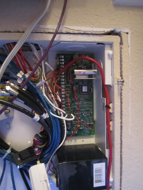
Now that these steps are complete, we can move on to hooking the unit into our panel. When I received my device, I debated about how I would hook it into my panel and to my Mac Mini, which are a good distance away from each other. Since the AD2USB is powered via the panel and not an external power source, and since the power requirements are a mere 30ma, the signal should easily travel hundreds of feet over Ethernet cable with no risk of signal loss. Since my house is prewired and my Ethernet patch panel sits next to my Ademco unit, running the signal over Ethernet was the perfect answer to my dilemma.
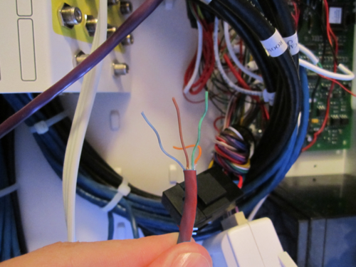
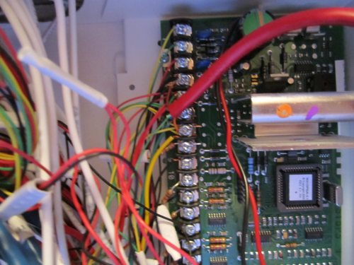
I cut a patch cord in half and then chose four wires to use for the connection and then cut the remaining wires so they would be out of the way. After choosing my four wires (one from each pair), I located the end of the unused “telco” cable from my office (where the Mac sits) in the patch panel (where the alarm is located). Then I connected the four wires from my patch cable to the alarm panel and then used an in-line RJ45 coupler to connect the wire from the panel and the wire from the office together. I then took the other half of the patch cable and, using the same four wires, connected it to the AD2USB (there is no circuitry in the AD2USB to protect from polarity reversal so BE CAREFUL!) and then inserted the RJ45 end of the cord into the open wall socket.


Step 4 – Connecting to the Mac and Testing
Now that the AD2USB was wired to the panel, I powered the Ademco unit back up.
Before I connected the USB cable to the Mac I needed to make sure I was able to distinguish the name of the device when I finally connected it to the computer. The best way to do this is to open a terminal session and then issue the following command:
ls -l /dev/cu.usbserial-*
I took note of what was returned and then connected the USB cable between the AD2USB and the computer then issued the above command a second time. At this point I could see my new device name. If you don’t then be sure that you installed the FTDI drivers as outlined in the installation instructions.
That’s it! The installation of the AD2USB was now complete. The first step to validating that it worked was to check that the unit was producing a “heartbeat signal” which I could see as a flashing green light on the AD2USB itself. If you don’t see the signal then go back and check your work.
My next step was to terminal into the unit and see if I could talk to it. To do this, I opened a Terminal session and then used the cu command to “dial up” my device:
sudo cu -l cu.usbserial-A2001wKL
After hitting enter a few times, Voilà! I could see the AD2USB spitting out ECP traffic.
In my next post, I’ll cover the steps necessary to integrate with Indigo.
Until then, geek out!
~GT~
