
WARNING: This post involves live mains electricity and is EXTREMELY DANGEROUS! Do not attempt this project on your own unless you are qualified to do so. I advise you to engage a licensed electrician to help you build this test unit!
Most of my electronics projects involve modern devices that require low voltage DC and minimal current. Occasionally I take on a project that involves high voltages, but these usually involve new components which run little to no risk of internal faults that involve dead shorts. This all changed when, in a moment of nostalgia, I bought an old Marantz Stereo Receiver off of eBay. I knew from the description that the unit was “dead” and when I received it and broke open the case, I could see that there were indeed indications of serious problems. After performing diagnostics and making a number of repairs (capacitors, transistors and fuses), I was ready to conduct a test to see if the unit was working. The proper way to do this would be to have an isolation transformer and a variac and to slowly bring up the power to make sure there were no shorts. Since I don’t do enough of these types of projects I thought it might be nice to build myself a Dim Bulb Tester instead.
A Dim Bulb Tester is a very simple device that puts an incandescent light bulb in series with power running into an unknown device which acts as a current draw if there is a short in the device being tested. Not only is it really simple to build, it’s a rock solid way to safely test “new” old gear without fear of doing damage in the event that there is a problem.
I wanted to keep the tester as simple as possible. I wanted one dual outlet receptacle with one socket used for the bulb load and the other socket serving up power to my test load. I also wanted a switch to make it really easy to prepare my tests and to kill power in a hurry if needed.
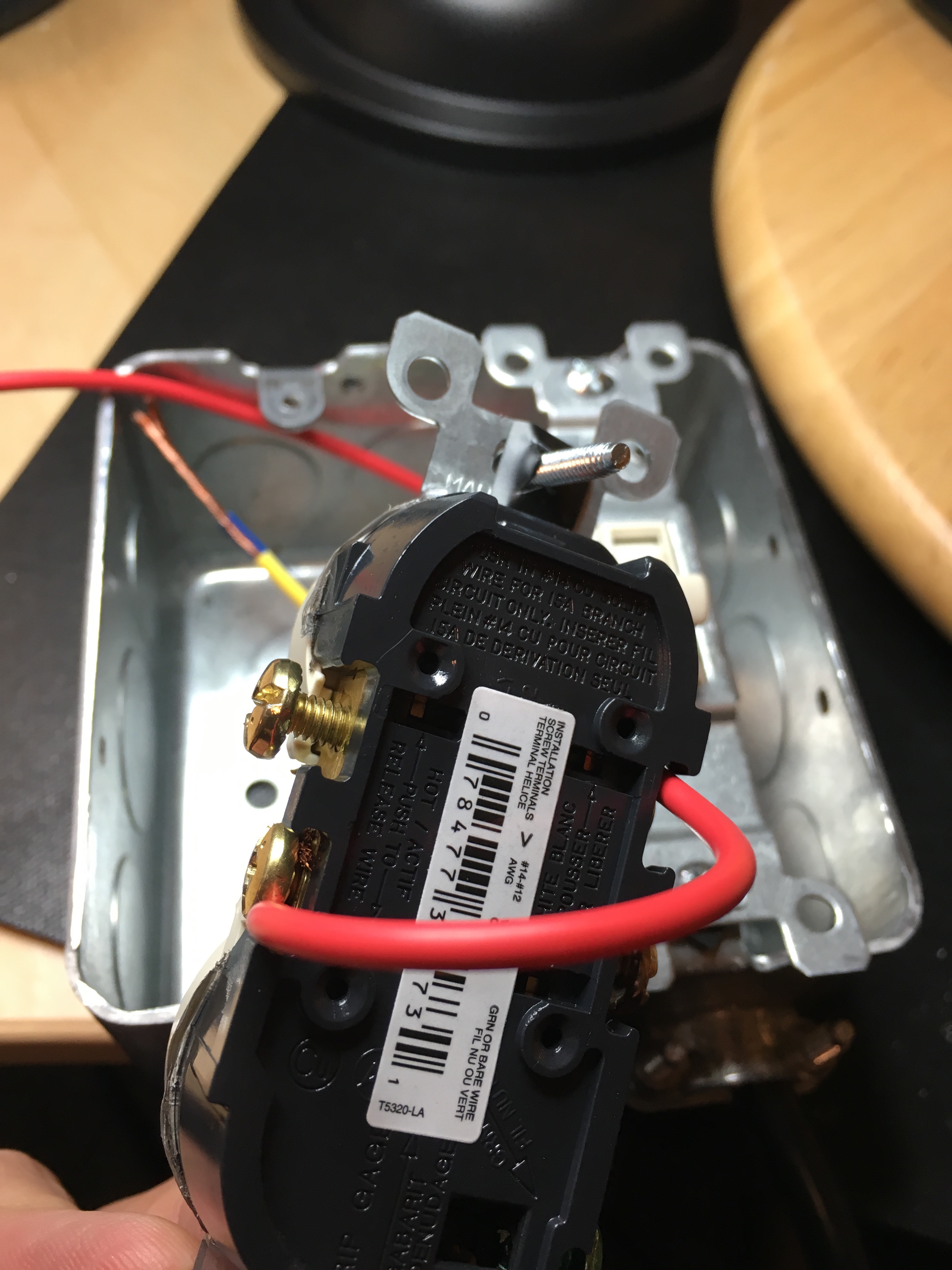
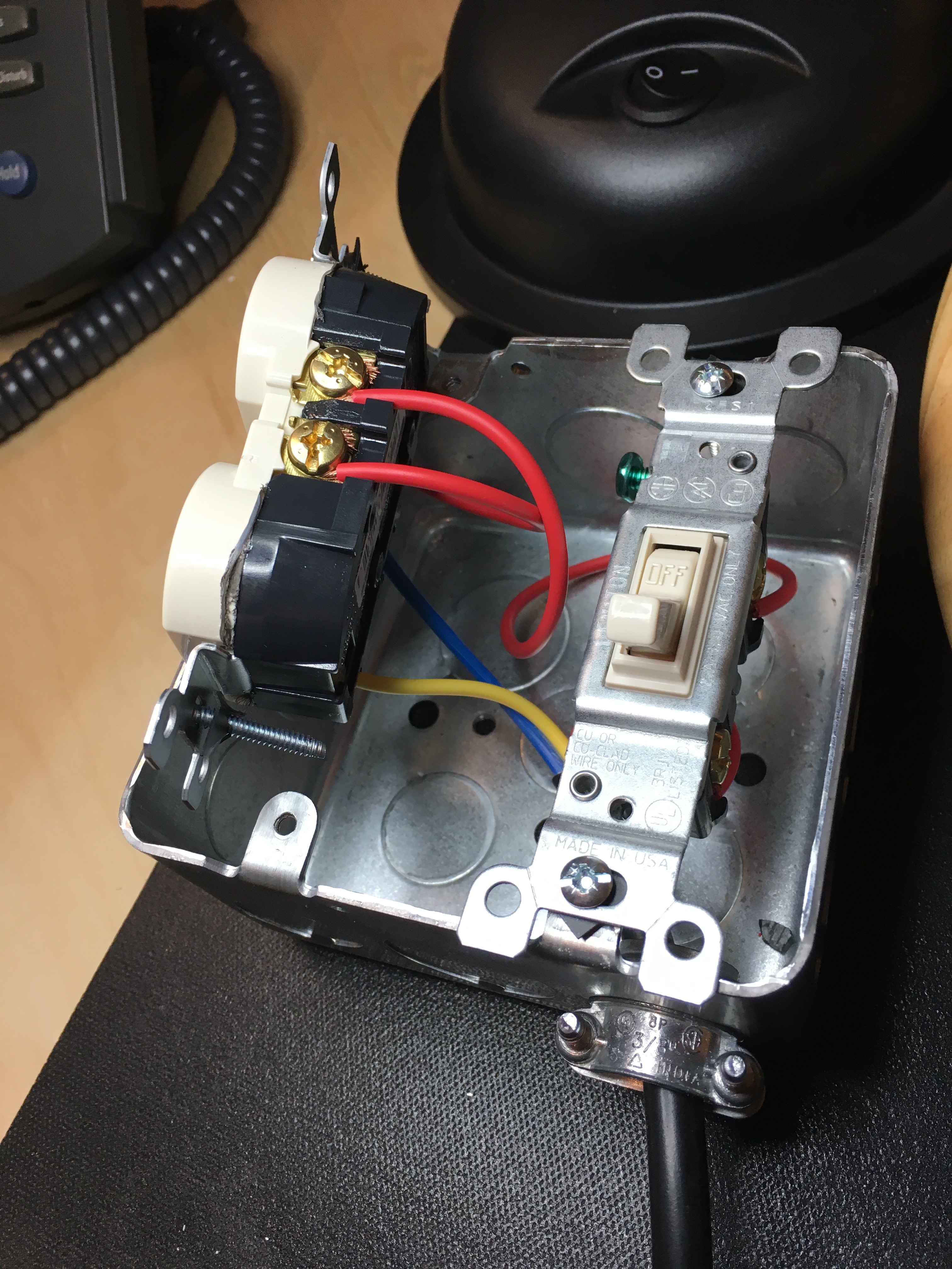
After purchasing my parts, the first thing I did was cut the tabs between the neutral and hot connections on each side of the duplex receptacle. This allows each socket to function independently and is critical to this particular circuit design.
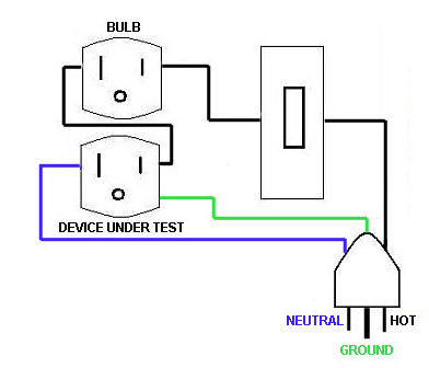
The next step involves wiring up the circuit. Even though the power in our homes is AC, most people don’t realize that that power is polarized. In other words, one lead is hot and the other is neutral. For safety reasons, we want to make sure we pay attention to how we hook these leads up in our circuit. This is particularly important when using a unit like this to test old electronic devices that use hot chassises such as All American Five radios and vintage TV sets. Wiring the circuit is very straightforward. Simply run the hot wire through the switch, through the bulb socket and then to the hot side of the load socket of our receptacle. Then connect the mains neutral to the neutral side of the load socket and, last, but not least, connect the ground to the duplex unit.
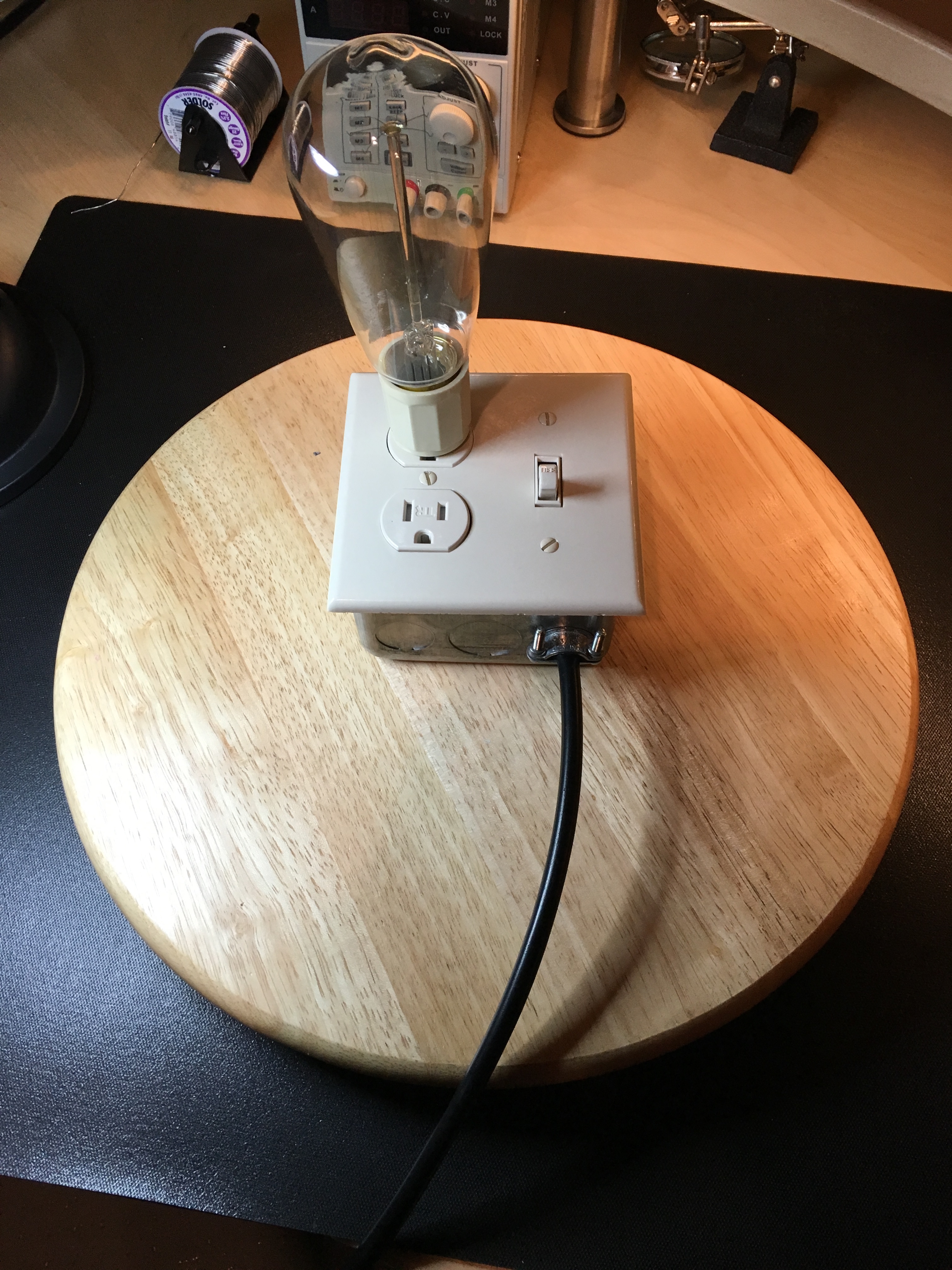
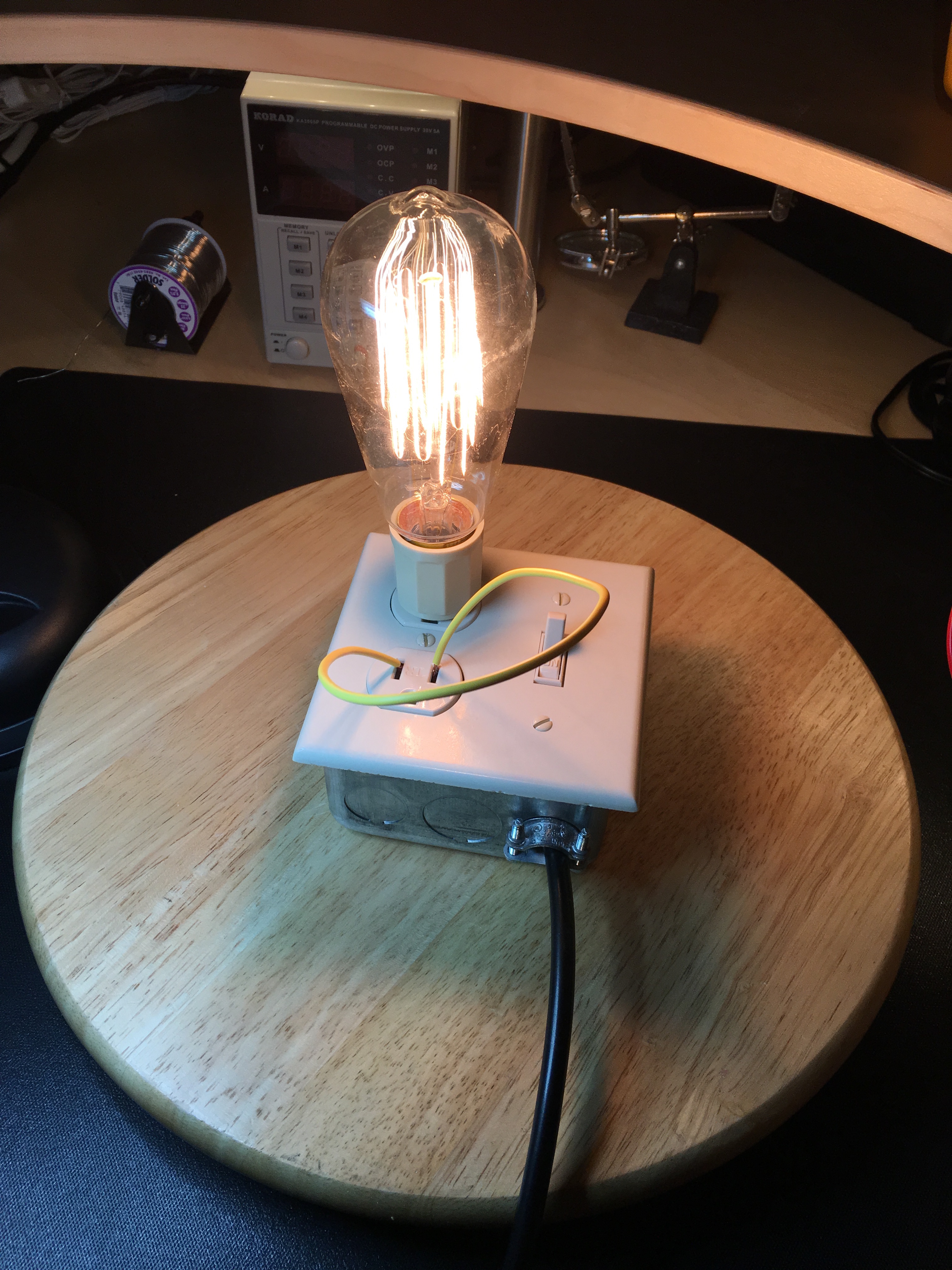
At this point, your Dim Bulb Tester is fully functional. Plug the unit into mains power and plug in a test load such as a lamp or radio. If you wired it up correctly, simply turn on the switch and the load should power up normally and the bulb will stay off. Now short the load socket (WARNING: Exercise EXTREME CAUTION!!!! DO NOT perform this test unless you know what you are doing! This is extremely dangerous!) and the bulb should light up.
It’s important to note that the incandescent light bulb you choose for your unit is important. First and foremost, the lower the impedance of your bulb the better. Secondly, the wattage of your bulb matters. If you’re goal is to test old HiFi gear from the 70s and 80s then a 40 watt bulb should be just fine. If you get into older vintage gear, here’s a guide that might help:
- 25 – 40 Watts = All American 5 Radio
- 40 – 75 Watts = 6 Tube w/Transformer
- 75 – 150 Watts = TV
- 200 – 350 Watts = Color TV
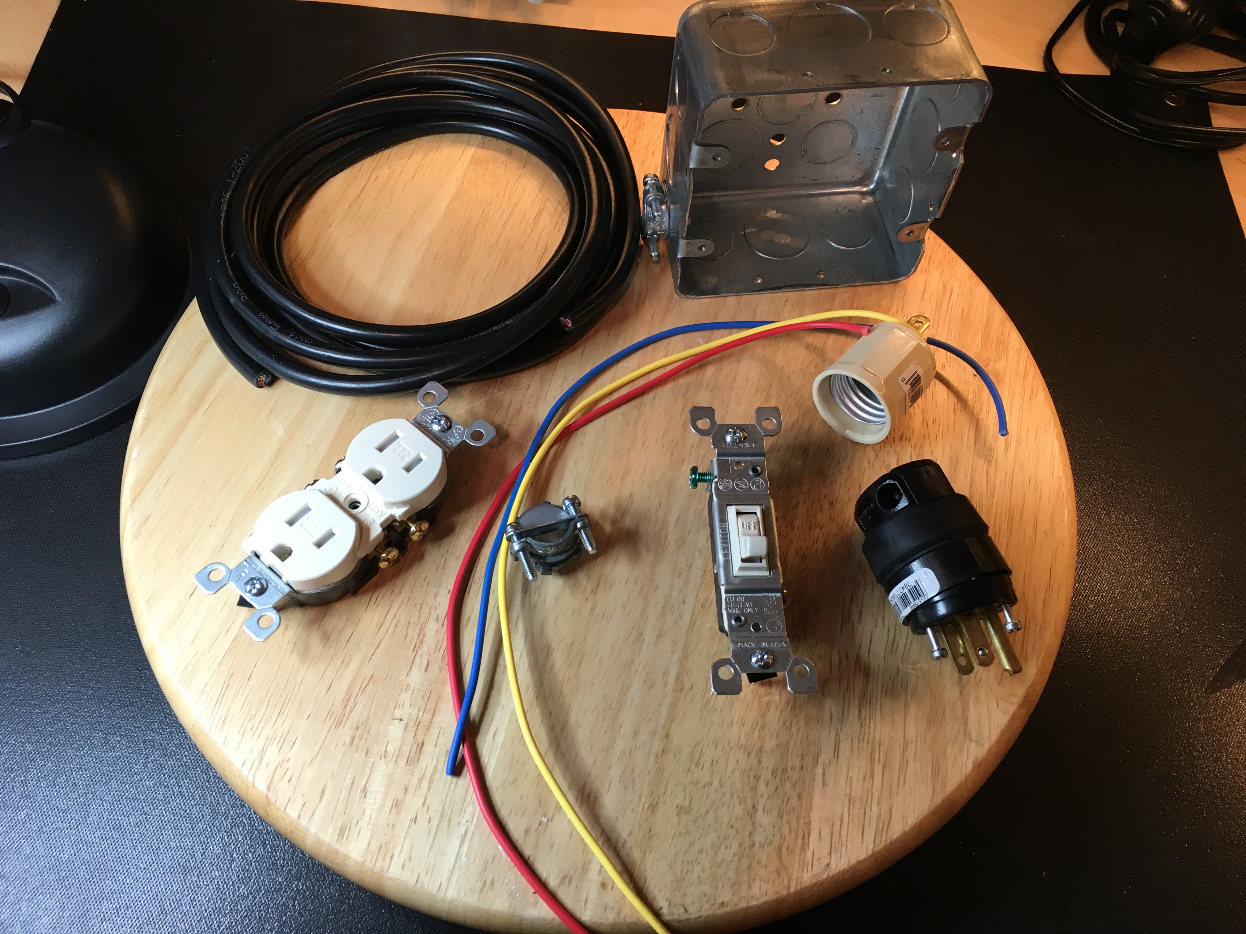
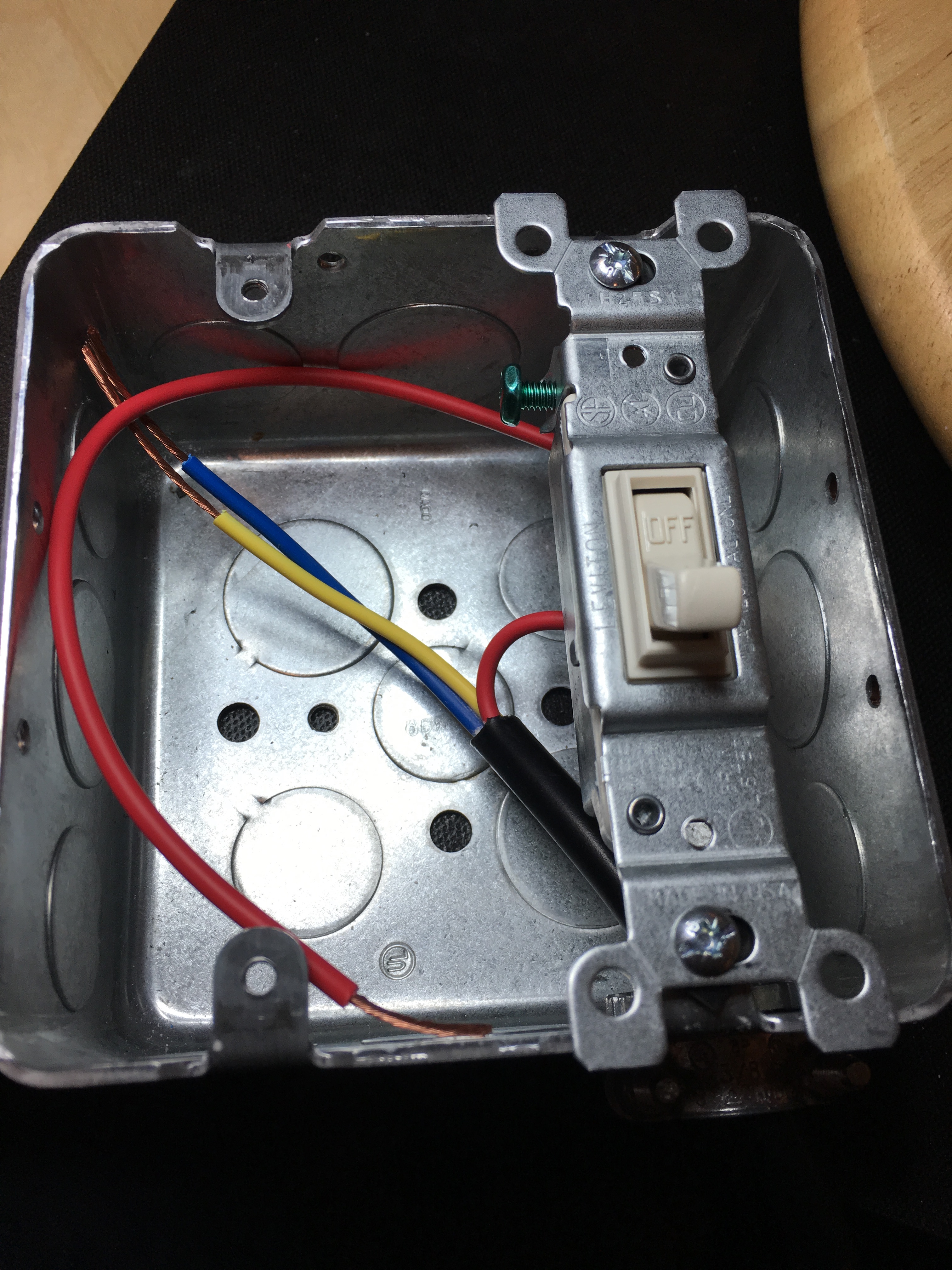
That’s it; so simple, yet so ingenious! Following are some images of my build.
Until next time – GEEK OUT!
~GT~
Could I buy a dim bulb tester from you? I’d like to check my vintage Pioneer SX-1980 receiver. I would prefer to use a dim bulb tester and not a variac. Let me know if you would be able to make me one. I am in Canada. I would sure appreciate it if you would be able to sell me one. Could you include one where you could increase the voltage with a variable dimmer?
I am looking for a dim bulb tester. My Pioneer SX-1980 has completely shut down and Jeff from Pacific Stereo has recommended that I get a dim bulb tester before I power it up again.
Here’s Jeff’s write-up
There’s our problem. The large resistor got hot and the thermal fuse opened to prevent a fire. The question now becomes why. The only reason that resistor can heat up is because it is not being bypassed by that relay. So that means:
1) The contacts on the relay are not good.
2) The relay is not being turned on
a) the power switch is not completing the circuit for the relay coil between pins 1 and 2 on the AWR-154 board, preventing operation
b) R102, the 3.3K resistor that feeds the relay coil is open or changed in value (R102 drops the 100 volts down to 48 or so under load)
c) bad 100V supply (open FU1, FU2, bad/open D204, D205, bad C204 taking out one or both of the fuses, some other load taking the supply out)
d) open relay coil (very unlikely)
3) Open trace between relay contacts and 3.3-ohm resistor.
That’s about it. I’m not sure how we should proceed, because one wrong move and something else can blow up. The board is removed by displacing the four outside hold-down studs and the one screw in the middle. But the board is very difficult to get out and can only be moved a little bit. To move it more means disconnecting wires. And then when you think it’s fixed, you have to put it all back. When you go to move it mark all the wires, and TAKE PHOTOS. That way you can see how routing works so you can actually get it placed back down, cause that’s a bitch, too.
I think probably the thing to do is to get you a new thermal fuse. The one you have can be bypassed for testing (fraught with peril, this makes me very nervous), but then we need to talk about how we bring the unit up for minimal testing. Does your guy have a dim bulb tester or a variac with a current meter on it? The problem here is that I just don’t know how to describe the “feel” of a normal startup when using a DBT or a variac. I know it when I see it, but can’t describe it for someone else. One thing for sure is that you’ll want to have the power amplifier sections disconnected when you power it up (when we get there). You’ll need a 150 watt (100 watt won’t; work as well) bulb for the DBT.
PROBLEM #1:
I do not know how to build a dim bulb tester. I would like on with a dialer to
Robert, Canada